---
title: Freqk Display
status: partially complete
references:
- https://github.com/nixpulvis/freqk
collection: projects
---
I own a Korg MS-20 Mini, and have been using it to learn a bit more about music
and signal generation. It has configurable oscilators, envelopes, and filters.
The primary way we interact with sound is with our ears, but electronic tools
can also be made to "hear" and then display that information visually. I've
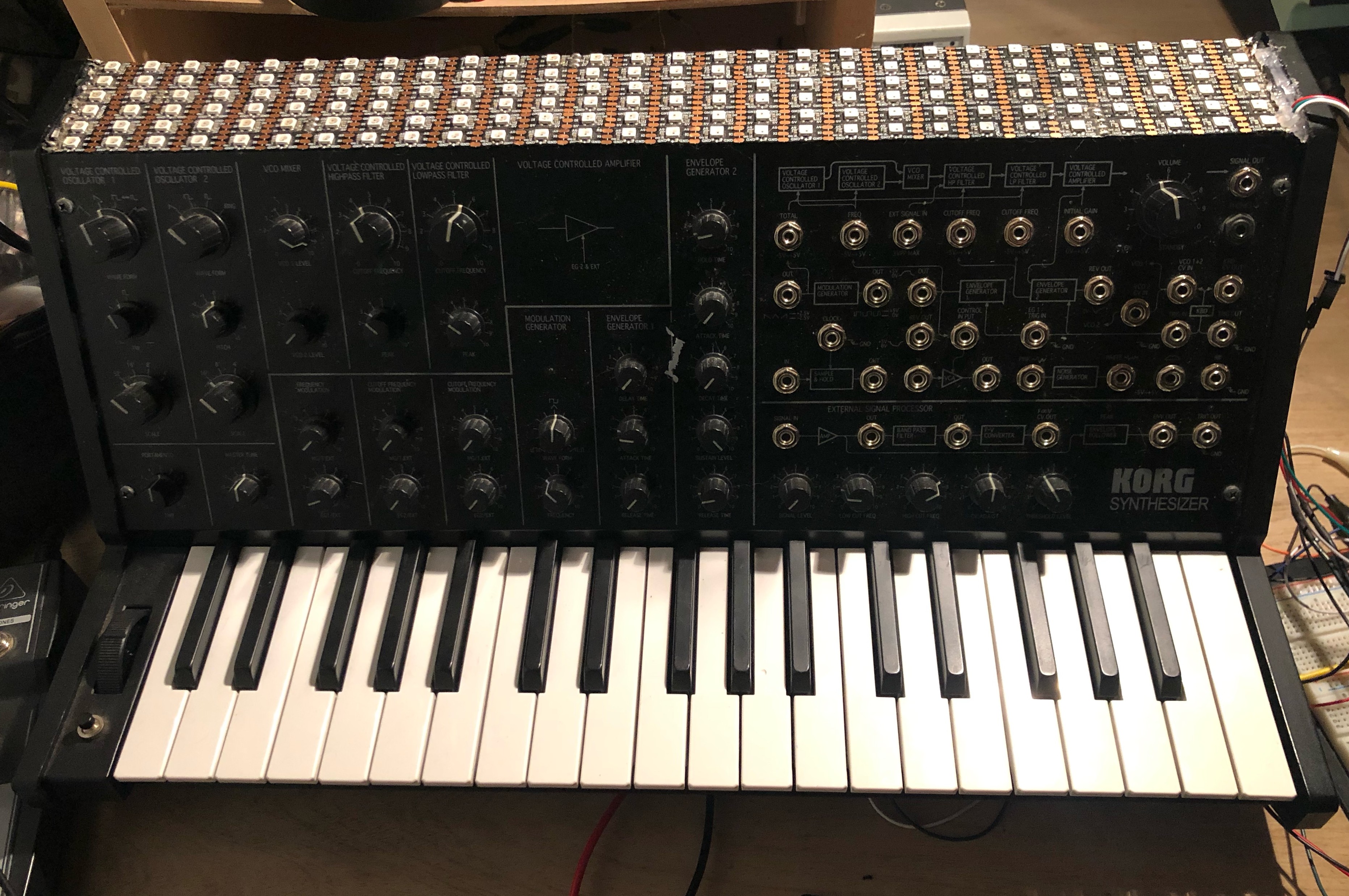
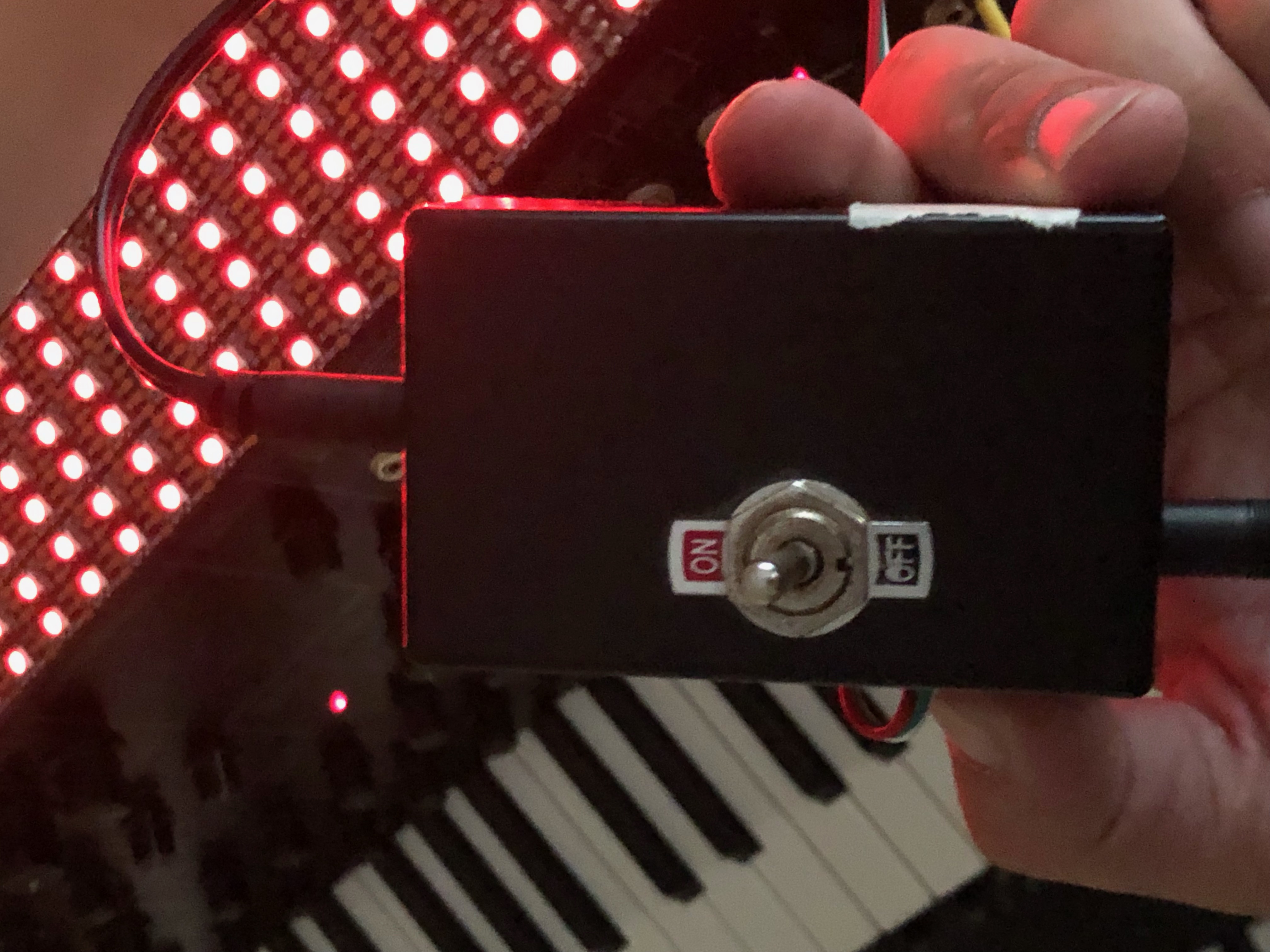
built an LED display (on top of the synth) to visualize the intensity of 7
frequency bands (4 LEDs) of our audible spectrum, log scale.
### Demonstration and Explaination
### Details
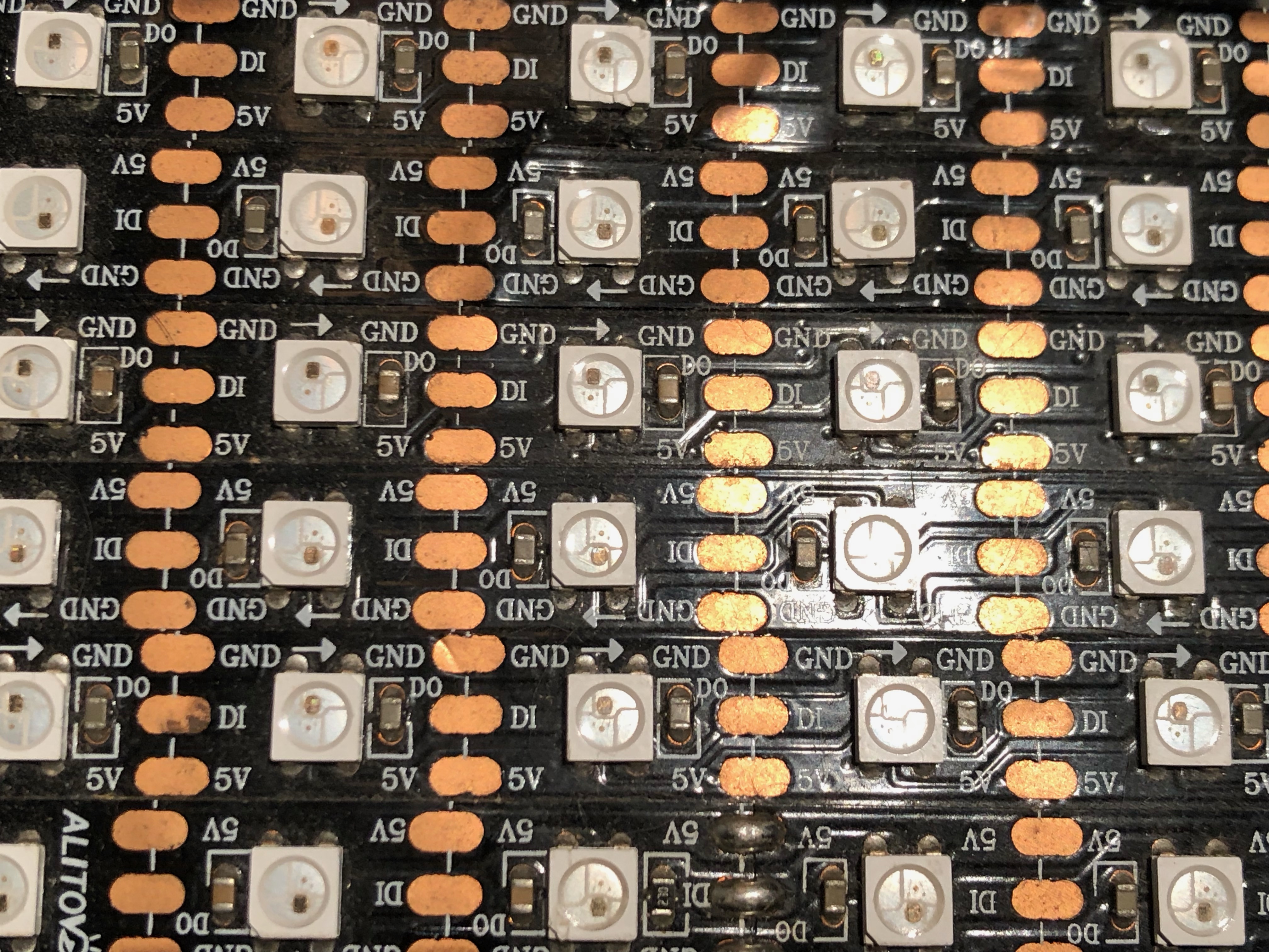
We have 28 LEDs along the width of the synth, going 15 deep back away from the
keys. Six on top and nine down the back.
```c
#define DISPLAY_WIDTH 28
#define DISPLAY_BAND_WIDTH 4
#define DISPLAY_TOP_DEPTH 6
#define DISPLAY_BACK_DEPTH 9
#define DISPLAY_DEPTH (DISPLAY_TOP_DEPTH + DISPLAY_BACK_DEPTH)
```
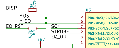
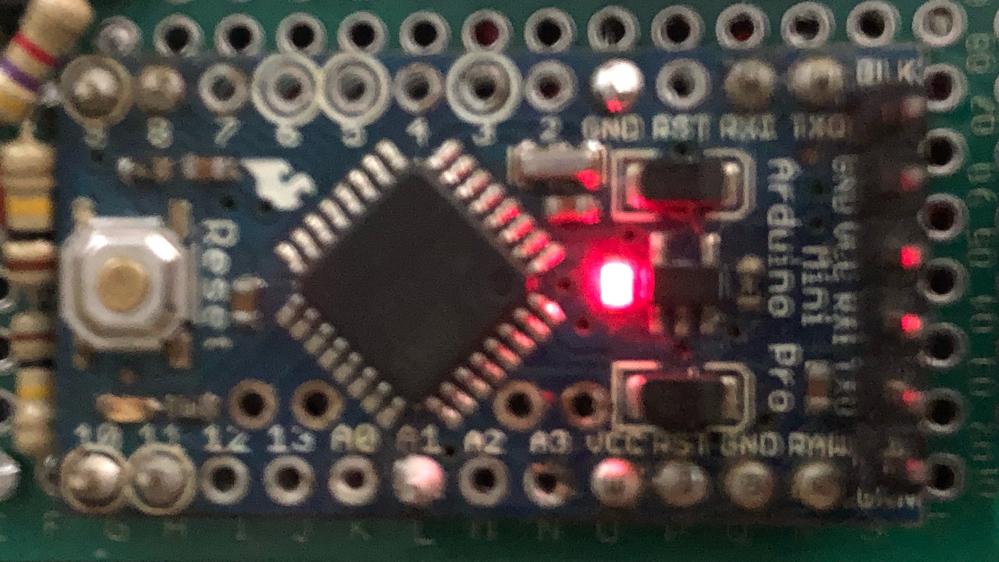
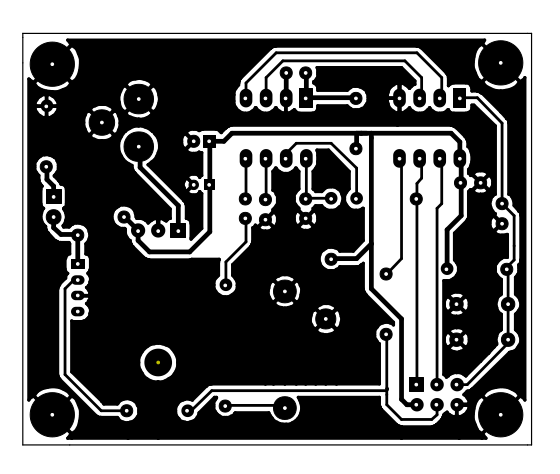
Using the Arduino has many advantages, but eventually I'd like to use the board
we etched by hand.
```c
#define ANALOG_PIN A1
#define STROBE_PIN 10
#define RESET_PIN 9
#define DISPLAY_PIN 8
```
```c
#define BANDS 7
```
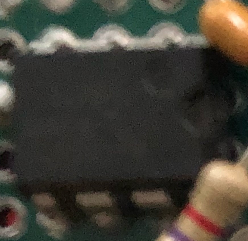
The MSGEQ7 has 7 bands which it samples for analog values.
### Main Loop (Overview)
This is a slightly simplified version of the `loop` function for the Freqk
Display.
```c
void loop() {
int spectrums[DISPLAY_DEPTH][BANDS];
read_msgeq7(spectrums[0]);
clone(spectrums);
update_display(spectrums);
}
```
### `read_msgeq7`
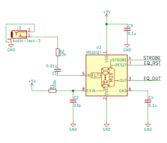
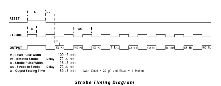
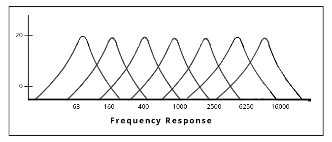
In order from first to last, the bands are centered around the following
acoustic frequencies: 63Hz, 160Hz, 400Hz, 1kHz, 2.5kHz, 6.25kHz, 16kHz.
```c
void read_msgeq7(int spectrum[BANDS]) {
// TODO: Dynamically set this value somehow?
int spectrumOffset[BANDS] = { 60, 74, 68, 60, 62, 60, 60 };
digitalWrite(RESET_PIN, HIGH);
digitalWrite(RESET_PIN, LOW);
for (int i = 0; i < BANDS; i++) {
digitalWrite(STROBE_PIN, LOW);
delayMicroseconds(90); // why was this working at 30?
spectrum[i] = analogRead(ANALOG_PIN) - spectrumOffset[i];
if (spectrum[i] < 0) spectrum[i] = 0;
digitalWrite(STROBE_PIN, HIGH);
}
}
```
### `clone` and `shift`
```c
void clone(int spectrums[DISPLAY_DEPTH][BANDS]) {
for (int s = 0; s < DISPLAY_DEPTH; s++) {
memcpy(spectrums[DISPLAY_DEPTH - s],
spectrums[0],
BANDS * sizeof(int));
}
}
```
Things get a little more complex for shifting and triggering, but the code is
still pretty straightforward.
First there are two configuration options. `HISTORY_TRIGGER`, if `HISTORY`
is enabled, will trigger a new shift when the value is exceeded in difference
on consecutive analog reads. A trigger value of 0 will cause updates to
happen consistently on every other cycle.
```c
#define HISTORY 1
#define HISTORY_TRIGGER 0
```
```c
#if HISTORY
void shift(int spectrums[DISPLAY_DEPTH][BANDS]) {
#if HISTORY_TRIGGER > 0
bool visable = false;
for (int i = 0; i < BANDS; i++) visable = visable || abs(spectrums[0][i] - spectrums[1][i]) > HISTORY_TRIGGER;
if (max_index(spectrums[0]) != max_index(spectrums[1]) && visable)
{
#elif HISTORY_TRIGGER == HISTORY_TIME
tick++;
if (tick % 2 == 0)
{
#endif
for (int s = 0; s < DISPLAY_DEPTH; s++) {
memcpy(spectrums[DISPLAY_DEPTH - s],
spectrums[(DISPLAY_DEPTH - s) - 1],
BANDS * sizeof(int));
}
}
}
#endif
```
### `update_display`
```c
void update_display(int spectrums[DISPLAY_DEPTH][BANDS]) {
int intensity;
int loudest_band;
for (int s = 0; s < DISPLAY_DEPTH; s++) {
loudest_band = max_index(spectrums[s]);
for (int b = 0; b < BANDS; b++) {
// Each strip is alternating direction as they connect Dins.
if (s % 2 == 0) {
intensity = map(spectrums[s][(BANDS - 1) - b], 0, 1024, 0, 255);
} else {
intensity = map(spectrums[s][b], 0, 1024, 0, 255);
}
for (int i = 0; i < DISPLAY_WIDTH / BANDS; i++) {
int display_index = (s * DISPLAY_WIDTH) + (b * DISPLAY_BAND_WIDTH) + i;
uint32_t color;
color = intensity_color(intensity, loudest_band);
display.setPixelColor(display_index, color);
}
}
}
display.show();
}
```
### Colors
```c
#define COLOR COLOR_MIXED
```
Given the audio intensity and the loudest band and return a color.
We take the audio intensity to change the light's intensity. We need to know
the loudest band to change the color of the whole strip.
```c
uint32_t intensity_color(int intensity, int loudest) {
int scaled_intensity = map(intensity, 0, 1024, 0, 255);
#if COLOR == COLOR_MIXED
switch (loudest) {
case 0:
case 1:
return display.Color(0, 0, scaled_intensity);
case 2:
case 3:
return display.Color(0, scaled_intensity, 0);
case 4:
case 5:
return display.Color(scaled_intensity, 0, 0);
default:
return display.Color(scaled_intensity,
scaled_intensity,
scaled_intensity);
}
#elif COLOR == COLOR_RED
return display.Color(scaled_intensity, 0, 0);
#elif COLOR == COLOR_GREEN
return display.Color(0, scaled_intensity, 0);
#else
return display.Color(0, 0, scaled_intensity);
#endif
}
unsigned int max_index(int spectrum[BANDS]) {
int max_v = INT_MIN;
int max_i = 0;
for (int i = 0; i < BANDS; i++) {
if (spectrum[i] > max_v) {
max_v = spectrum[i];
max_i = i;
}
}
return max_i;
}
```
### Setup and Loop (Revisited)
## Next Steps
- Think about display mode inputs
- Investigate power and hardware requirements for back LED strips
- Firmware for etched board
- [GitHub Issues](https://github.com/nixpulvis/synth/issues)
 ```c
#define ANALOG_PIN A1
#define STROBE_PIN 10
#define RESET_PIN 9
#define DISPLAY_PIN 8
```

 ```c
#define BANDS 7
```
The MSGEQ7 has 7 bands which it samples for analog values.
### Main Loop (Overview)
This is a slightly simplified version of the `loop` function for the Freqk
Display.
```c
void loop() {
int spectrums[DISPLAY_DEPTH][BANDS];
read_msgeq7(spectrums[0]);
clone(spectrums);
update_display(spectrums);
}
```
### `read_msgeq7`

In order from first to last, the bands are centered around the following
acoustic frequencies: 63Hz, 160Hz, 400Hz, 1kHz, 2.5kHz, 6.25kHz, 16kHz.

```c
void read_msgeq7(int spectrum[BANDS]) {
// TODO: Dynamically set this value somehow?
int spectrumOffset[BANDS] = { 60, 74, 68, 60, 62, 60, 60 };
digitalWrite(RESET_PIN, HIGH);
digitalWrite(RESET_PIN, LOW);
for (int i = 0; i < BANDS; i++) {
digitalWrite(STROBE_PIN, LOW);
delayMicroseconds(90); // why was this working at 30?
spectrum[i] = analogRead(ANALOG_PIN) - spectrumOffset[i];
if (spectrum[i] < 0) spectrum[i] = 0;
digitalWrite(STROBE_PIN, HIGH);
}
}
```
### `clone` and `shift`
```c
void clone(int spectrums[DISPLAY_DEPTH][BANDS]) {
for (int s = 0; s < DISPLAY_DEPTH; s++) {
memcpy(spectrums[DISPLAY_DEPTH - s],
spectrums[0],
BANDS * sizeof(int));
}
}
```
Things get a little more complex for shifting and triggering, but the code is
still pretty straightforward.
First there are two configuration options. `HISTORY_TRIGGER`, if `HISTORY`
is enabled, will trigger a new shift when the value is exceeded in difference
on consecutive analog reads. A trigger value of 0 will cause updates to
happen consistently on every other cycle.
```c
#define HISTORY 1
#define HISTORY_TRIGGER 0
```
```c
#if HISTORY
void shift(int spectrums[DISPLAY_DEPTH][BANDS]) {
#if HISTORY_TRIGGER > 0
bool visable = false;
for (int i = 0; i < BANDS; i++) visable = visable || abs(spectrums[0][i] - spectrums[1][i]) > HISTORY_TRIGGER;
if (max_index(spectrums[0]) != max_index(spectrums[1]) && visable)
{
#elif HISTORY_TRIGGER == HISTORY_TIME
tick++;
if (tick % 2 == 0)
{
#endif
for (int s = 0; s < DISPLAY_DEPTH; s++) {
memcpy(spectrums[DISPLAY_DEPTH - s],
spectrums[(DISPLAY_DEPTH - s) - 1],
BANDS * sizeof(int));
}
}
}
#endif
```
### `update_display`
 
```c
void update_display(int spectrums[DISPLAY_DEPTH][BANDS]) {
int intensity;
int loudest_band;
for (int s = 0; s < DISPLAY_DEPTH; s++) {
loudest_band = max_index(spectrums[s]);
for (int b = 0; b < BANDS; b++) {
// Each strip is alternating direction as they connect Dins.
if (s % 2 == 0) {
intensity = map(spectrums[s][(BANDS - 1) - b], 0, 1024, 0, 255);
} else {
intensity = map(spectrums[s][b], 0, 1024, 0, 255);
}
for (int i = 0; i < DISPLAY_WIDTH / BANDS; i++) {
int display_index = (s * DISPLAY_WIDTH) + (b * DISPLAY_BAND_WIDTH) + i;
uint32_t color;
color = intensity_color(intensity, loudest_band);
display.setPixelColor(display_index, color);
}
}
}
display.show();
}
```
### Colors
 ```c
#define COLOR COLOR_MIXED
```
Given the audio intensity and the loudest band and return a color.
We take the audio intensity to change the light's intensity. We need to know
the loudest band to change the color of the whole strip.
```c
uint32_t intensity_color(int intensity, int loudest) {
int scaled_intensity = map(intensity, 0, 1024, 0, 255);
#if COLOR == COLOR_MIXED
switch (loudest) {
case 0:
case 1:
return display.Color(0, 0, scaled_intensity);
case 2:
case 3:
return display.Color(0, scaled_intensity, 0);
case 4:
case 5:
return display.Color(scaled_intensity, 0, 0);
default:
return display.Color(scaled_intensity,
scaled_intensity,
scaled_intensity);
}
#elif COLOR == COLOR_RED
return display.Color(scaled_intensity, 0, 0);
#elif COLOR == COLOR_GREEN
return display.Color(0, scaled_intensity, 0);
#else
return display.Color(0, 0, scaled_intensity);
#endif
}
unsigned int max_index(int spectrum[BANDS]) {
int max_v = INT_MIN;
int max_i = 0;
for (int i = 0; i < BANDS; i++) {
if (spectrum[i] > max_v) {
max_v = spectrum[i];
max_i = i;
}
}
return max_i;
}
```
### Setup and Loop (Revisited)

## Next Steps
 - Think about display mode inputs
- Investigate power and hardware requirements for back LED strips
- Firmware for etched board
- [GitHub Issues](https://github.com/nixpulvis/synth/issues)